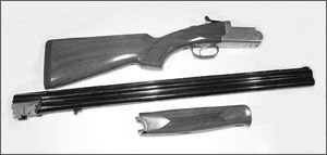


This new Savage over/under is made in Brescia, Italy. This northern area of the country is known for the manufacture of fine quality shotguns, and this one is no exception. Produced to meet Savage’s exacting specifications, the weight distribution of the Milano is perfect. Its 12-, 20-, 28-, and .410-gauge actions are precisely scaled to their gauge, and each one wears a handsome Turkish walnut stock finished off with satin lacquer. Among its standard features are automatic ejectors, chrome-lined barrels, lengthened forcing cones, a fiber-optic front sight paired with a brass, mid-rib bead, and a single selective trigger. Screw-in chokes? Of course, except for the .410; its 28-inch barrels come in fixed, modified, or improved cylinder.
300
The shotgun’s single selective trigger is mechanical rather then recoil-operated. I think you may agree with many shooters, especially those who kill hundreds of clay birds, that mechanical resetting is better than recoil. With recoil, the second barrel won’t discharge if the first barrel fails to fire. The mechanical reset in the Milano eliminates this kind of frustration. If the first barrel holds a dud, you simply pull the trigger again to fire the second.
The moment I saw the Milano at the 2006 SHOT Show, I added it to my “articles-to-do” list, but it took nearly a year before one came my way. The delay wasn’t because Savage Arms was being uncooperative; the problem was that the guns were coming in from Brescia one day, given a test fire and a quality check, and then shipped out the next day to waiting distributors. (Gun writers always have this problem when a hot new shoulder arm or handgun comes on the scene.)
There was yet another factor contributing to the long wait. Brescia was handling all the production. Sure, they were following Savage specs, but no one from Savage Arms was on the scene looking over the shoulders of the technicians who assembled the Milano for final shipment. As a result, it took additional time for the Massachusetts-based technicians who’d be servicing the shotgun to get up to speed with its function, how it comes down, how it goes back together, et cetera, et cetera.
I didn’t mind waiting, however. That’s because the rule I’ve followed in the 12 years I’ve been writing these disassembly/reassembly articles is this: There’s only one right way to do it, and that’s the way the factory does it. And it’s a good rule. Adhering to this rule has kept me—and, hopefully, you— free from all manner of unpleasantness. Moreover, it has saved manufacturers and their service personnel considerable time by not having to diagnose what might be wrong with a firearm taken apart by its owner, dropped into a plastic bag, and handed to an innocent gunsmith for reassembly.
It was Carl Hildebrandt, one of Savage Arms’ senior engineers—he answers the phone as “The Factory Guy”—who worked with me on this and all the other pieces I’ve written about the Savage products. And it was Carl and his top gunsmith who combined to develop the instructions on the Milano that I’m about to pass on to you. Thanks, guys.
Before moving further into those instructions, a suggestion is much in order: In detail stripping the shotgun, make a slave pin to substitute for every pin you remove. You’ll need them to retain parts in place during reassembly, and many of those parts will have been under pressure exerted by one spring or another. A second recommendation is equally important: Keep track of which firing pin, sear lever, and so forth is taken from the top side of the action, which is taken from the bottom, and which from the right or left side of anything. Don’t get them mixed up.
725
Basic Field Stripping
The shotgun is unloaded, the trigger has been pulled to lower the hammers, the safety is on, and you’re wearing safety glasses. Okay? In the center of the underside of the forearm is a release lever located in an oval depression in the wood. Pull the lever toward the rear of the gun. At the same time—or close to it—pull the front end of the forend away from the barrels. Move the top lever to the right, open the action, and lift the barrels free.
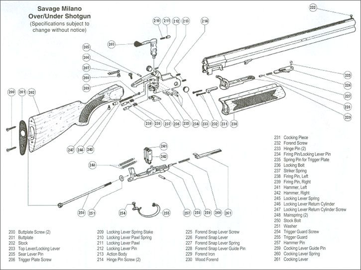
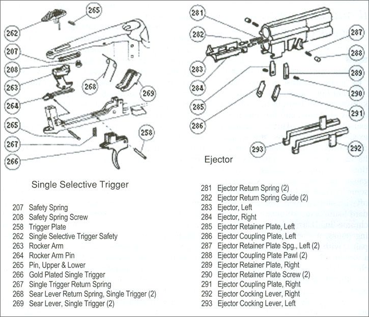
Detailed So, besides a good assortment of drifts and other small tools, what do you need standing by to disassemble a Milano? You’ll need a 7/16-inch socket, a long extension for the socket wrench, a #2 Phillips-head screwdriver, and a large plastic bag. Remove the recoil-pad screws (#200) after dipping the #2 Phillips head into a jar of Vaseline. Separate the recoil pad (#201) from the stock (#202). Check the socket in the stock-bolt hole for clearance between the socket and the wood. If it’s a tight fit, grind down the outside of the socket until there’s enough room in there to get hold of the stock bolt (#250) without taking a chance of cracking the wood. Back out the bolt along with the stock washer (#251). Now pull the stock to the rear to disengage it from the frame. The hammers should still be in the fired position. Remove the upper pin (#265) that retains the safety assembly, and remove the assembly from the upper tang. You’ve just exposed a screw (#206). Remove it and the trigger-plate pin (#235), and then tilt the rear of the trigger plate (#258) away from the frame.
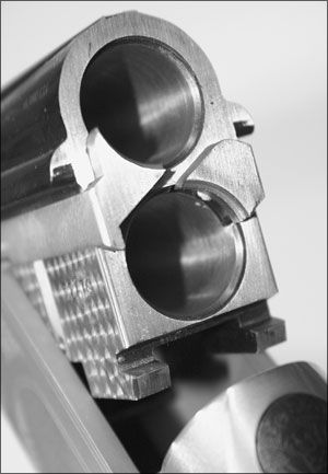
The mainspring assemblies (#248) can be removed by rotating the hammers forward and releasing the mainspring plungers from their seats in the rear of the hammers. They are removed from the frame to the rear. Don’t disassemble them further. When replacing, insert the rear of the assembly into its frame hole, move the sear lever up and the hammer as far forward as possible, and then pry the front end of the plunger onto the back of the hammer and into its hammer seat. Note: An unlikely circumstance could arise—a broken plunger spring—where just the mainspring assembly needs to be removed. This can be done without taking off the lower tang. With the hammer rotated forward, use a small tool to lever the plunger out of the hammer, and then move it upward and forward to separate it from the frame. Now for the lower tang. Remove the trigger-guard screw (#254) from the top to free the rear of the guard. The rocker arm (#263) pivots on a ball at its bottom that rides in a matching cup on top of the trigger. It’s held in position by the rocker-arm spring (#264). Being careful not to damage the spring, you can remove the rocker arm by rotating it forward and sliding it between the spring’s arms. Unless the spring must be replaced, I advise you not to remove it; it’s under tension as assembled. If replacement is required, however, position the spring against the tension provided when its tails are placed against the frame, and secure it there with its pin. Turn the trigger guard to the side. Remove the trigger (#266) and spring (#267) by drifting out the pin numbered 258 on the selective trigger schematic. There is no number for this pin and #258 on the main schematic parts list is the lower tang. Note that there are two pivot-pin holes in the trigger plate to accommodate differing trigger mechanisms. The single selective trigger in this Milano uses the front hole. 300 Unscrew the guard by rotating it out clockwise. Remove the left hammer (#241) and the right hammer (#242) by drifting out their pin (#257). Keep this in mind: The left hammer must be reinstalled in the trigger plate from whence it came. So must the right hammer. Otherwise, neither will fit or function. Though the firing pins can be removed and replaced while the trigger plate is in place, normally they are not. Begin by drifting out both pins (#234). This frees the firing pins (#238 and 239) plus their springs (#237). The firing pins differ slightly one from the other. Mix them up? Not! They go back in the same hole from which you took them. After the firing pins and springs are removed, place the frame in a large plastic bag before going after the locking lever (#203). You’re about to encounter parts that are under spring tension. Back out the locking-lever return cylinder screw (#247). This releases the locking lever cylinder (#246), lever spring (#245) and spring stake (#206) into the bag. Replacing these parts is a mean job even for factory gunsmiths. Like the guys at Savage, you’ll have to figure out a way of getting them back together that works for you. (I advise you to do some advanced planning as you take the gun down.) After removing the locking-lever pin (#234) and trigger-plate pin (#235), note how the slot in #234, a roll pin, orients to the bottom. It must be in the same position when reinstalled to retain freedom of movement for the locking lever. Now push the locking-lever pawl (#211) flush with the front of the lever and clear of the frame. Lift and turn the lever while retaining the pawl and its spring in the lever to disengage the locking bolt (#236). Remove the locking bolt to the rear. The ejector cocking levers (#292 & 293) slide rearward and out of the frame through the opening for the trigger plate. Before going after the sear levers (#269) and sear-lever springs (#268), study how the springs are positioned under tension. Plan ahead. They have to be in the same position for reassembly; a slave pin will be the thing that holds them there. 300 When you removed the barrels, you may have noticed two screws visible on the frame’s pivoting surface. These are the hinge-pin screws (#214). Backing them out will—not surprisingly—free the hinge pins (#233). The forend iron (#229) is attached to the forend by two more Phillips-head screws (#232). The forend-snap lever (#226) is attached to the forend by its screw (#225). The head of this screw is in a clearance on the top of the iron to allow lateral movement. The snap lever itself retains its spring (#227) and guide pin (#228). Beware of a flying spring when you remove the lever. At the rear of the iron is the cocking piece (#231). It’s been driven into a dovetail slot and staked there. Unless it is damaged, leave it alone. I want to expand some on the barrel assembly. The tubes are fitted in a monoblock and have a vented top rib. The light-gathering front site is screwed into the rib. The mid-site is driven in, and a strong adhesive used to secure it in place. In disassembly of this section, remember the “which is right and which is left” rule. The ejector/extraction system is housed within the monoblock but activated by the frame and cocking levers. The left ejector (#283) and right ejector (#284) are retained in the block by a left retainer plate (#285) and ejector plate right (#289), both of which are secured by ejector plate screws (#290). As factory assembled, the ejectors are under pressure from the ejector springs (#281) and their guides (#282). Their function as an extractor or as an ejector is determined by the ejector coupling plates (#286 and #291). These are set to catch the ejector when a barrel is fired by the ejector cocking levers. A cocking lever matching the fired barrel is moved forward by that barrel’s hammer to raise that ejector’s coupling plate. This holds the ejector in place as the action is opened. The ejector so held will remain held until the barrels are almost clear of the breechface. Then a surface on the frame cams the retaining plate out of engagement with the ejector and out flies a spent hull. None of this happens with a barrel containing a live or dud round. In that case, the coupling plate of the barrel’s ejector is held in the lower position, allowing the ejector to move back under spring pressure and serve as an extractor. And that, my friend, is how the ejector/extractor system of the Milano’s single selective trigger works. But wait a minute, there’s more. To remove the ejectors, press them into the monoblock to catch them by the coupling plate. Unscrew part #290 until the plate can be lowered in its dovetail slot. Remember that an ejector is under spring pressure as you release it from the block. Once it’s out, remove the ejector-guide pin and spring. As is often said—and, in this case, is true—reassemble in reverse order. And I hasten to add, don’t forget to use those slave pins and that plastic bag. Otherwise, plan to waste an hour or more in fruitless searching.
Disassembly