During World War II, American troops didn’t have the luxury of time to learn much beyond the basics of shooting. Most everybody could be taught to shoot a rifle in a few weeks, and that served the military’s needs. But officers were to carry .45s, and the military quickly found that not everyone could learn to shoot one well enough to hit anything in such a short time.
So, rather than spend extra days and weeks teaching young lieutenants to handle their 1911 properly, the M1 Carbine was introduced. Rifles were easier to learn and shoot than handguns. Thousands were produced and sent all over the world during the war. In the succeeding years, it seems like the M1 Carbine has been in just about every country that could be considered a U.S. ally. And today, given the American shooter’s interest in things military, many of the guns are coming back here.
They are coming home in just about every condition you can think of. Some of the rifles that have spent time in Third World countries look like they’ve been worked more by blacksmiths than gunsmiths. These repairs, modifications, and handmade parts are very interesting, but usually need to be redone.
M1 Carbine manufacturing didn’t stop at the end of World War II, continuing in various forms for several years thereafter for both commercial sales in the U.S. and for foreign military use. Universal’s version was revised to allow cheaper and easier manufacturing. Iver Johnson followed the military pattern more closely but even then made variations to cut production costs.
For our discussions here, we’ll work from the U.S. military rifle, referring to variations in the other rifles only as necessary to make repairs. Not even all the military guns were the same, so don’t be surprised if you find something we didn’t mention on the gun you’re working. We’ll leave the M2 model alone because, while the parts interchange with the M1, it is a restricted Class III firearm.
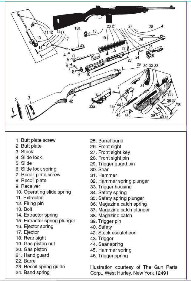
Disassembly
The barrel band retaining spring face on the right side of the forearm is very stiff and must be pushed inward to release the barrel band. Before attempting to remove the barrel band, unscrew the barrel band screw. While holding this spring in, you must push the band forward toward the muzzle for it to clear its retaining spring. As soon as it clears, you may release the retaining spring and push the band far enough to clear the forearm. Remove the handguard from the barrel by sliding it forward. With the magazine out of the rifle, you can lift the barrel out of the forearm. This releases the locking lug on the back of the receiver so the entire action can be removed from the stock.
The trigger guard retaining pin just forward of the magazine well is easily driven out, but it occasionally varies in style. Some can be driven from either side, while others have a head that makes them come out in only one way. Most are machined, and you can see the pin’s head when it is larger than the body. Trigger guards that are limited by plate steel have their pins recessed into the guard, restricting the direction they can be driven out as well. These rifles have been taken apart many times, so there is no telling which pins are in which rifles or from which side they were inserted. Because of this, do not drive the pin with too much force from one side until you have also tried it from the other. You may have disassembled a hundred of these and never run across one with a head or a recessed one, but forcing one is sure to find the first. Slide the trigger guard to the rear and it will release from the receiver.
Laying the trigger housing aside for now, we will remove the slide from the receiver. The slide spring and guide are removed by gripping the front end and pulling to the rear enough to release it from the slide. Pull the front end away from the slide and slowly release the spring’s tension. Take it out of the receiver by pulling forward until it releases. There is a 4 inch slot cut into the right side of the receiver that the butt end of the slide rides in. Two and one half inches from the muzzle end of this slot is a notch cut into the top of the slot. This is the disassembling slot, not the smaller one an inch closer to the butt. A corresponding lug on the very back end of the slide right under the charging handle locks into this slot. Pull the slide back with the charging handle until it just covers this slot and lift the charging handle enough for it to release from the slot. It may be necessary to wiggle it around but it will release. Letting the locking lug ride on the outside of the slot, push the slide up and forward and it will release from the bolt. Moving an inch forward from the spot that released the slide from the receiver will release the front of the slide from the rail on the bottom of the barrel. The slide will then come off and can be lifted out of the receiver.
Now that we’ve field-stripped the rifle for cleaning, let’s check for problems. Since the bolt usually needs the most attention, let’s start with it.
The guns are often in terrible shape when they make it back to the U.S., something that has prompted many people to refinish them as cheaply as possible because a good blueing job costs about as much as the rifle. I have seen such jobs done where the bolt remained fully assembled and was then soaked in oil to stop the corrosive effects of the re-blueing or parkerizing.
You can tell if this has happened when you take one of these bolts apart. The springs will be gritty, and the ejector and extractor holes will be rough inside. They will need to be thoroughly cleaned and the springs replaced. The firing pin may or may not show the same signs, but always clean its cavity very well.
The extractor, secured by a spring and detent ball, is the most commonly replaced part on the M1 Carbine. The ball must be held down and out of the way for the extractor to be removed. Use a punch to drive it out through the bottom of the bolt. Go slowly; when you have driven it less than a quarter-inch, the ejector plunger and spring will be released out of the bolt face with great force. The firing pin will also come out after the extractor is removed.
If the rifle will not extract a fired round, the extractor lip that holds the cartridge rim is often chipped or broken off. This lip should be not be rounded off on the bottom gripping edge. If you have to replace it, be sure the new one is the same size and shape as the original. Many cast extractors sold at gun shows or by mail are no better than pot metal and often do not fit.
On bolts that are rusty or have been improperly re-blued or parkerized, the ejectors often stick or move so slowly that they will not have sufficient force to clear the fired cartridge. Stovepipe jams are the most common symptom of this problem.
We rarely find broken firing pins, but they sometimes have to be replaced. The pin should extend just far enough to ignite the primer of a cartridge that is locked full against the bolt face by the extractor. Home- or foreign-made firing pins will sometimes protrude too much and are potentially dangerous. This can sometimes, but won’t most of the time, cause the rifle to fire on closing. You will also occasionally run into one of these rifles that has been modified in an attempt to create auto fire. You are required to notify the Bureau of Alcohol, Tobacco and Firearms if you find such evidence.
Slides must be checked and often need work but seldom need to be replaced. The slide lock is located just inside the charging handle, but on many of these rifles, it is gone. (On some commercially made rifles, the slide lock is a small lever located just under the windage adjustment knob on the rear sight.) This piece is installed through the bottom and held in place by a spring and detent ball seated in a hole drilled into the charging handle. As with the bolt assembly, the most common problems are created by cheap refinishing attempts. Solve this problem in the same way we did with the bolt.
The slot cut inside the slide’s arm to hold the bolt lug is sometimes hammered until it has a sharp metal ridge on the top front edge. This is where the bolt slams to a stop against the bolt lug as it turns up into the release position. This can be filed away, but do not remove any metal from the front or rear of this slot. Check the two guide rails‚one where the arm joins the body of the slide, the other just across it‚inside the body. If either is broken, the slide must be replaced. While you’re at it, check the corresponding rails on the bottom of the barrel. They must be clean and sharp without dents or missing metal. Also inspect the inside of the receiver assembly for missing metal.
The gas piston is located on the bottom of the barrel 4 inches in front of the receiver. The Army made a special wrench to remove the piston nut, and removing it by any other manner requires great care. A dented piston will walk around while the gun is fired and ultimately‚when the dent works under the arms of the nut‚the breech will fail to open or won’t open with full force.
Almost every feeding and ejection problem usually associated with other parts of the rifle can also be created by the dented piston nut, but you still see those that have been hammered out with a punch or screwdriver. Stories have gone around for 50 years about removing these with a bayonet and rock during the war, so it is hard to convince people not to pound on them. The piston wrenches are inexpensive and plentiful as well as easy to make. If you still insist on using something other than a wrench, be careful and apply pressure to at least two of the three piston nut arms when removing it. Not to dwell on cheap refinishing, but it also applies here. After the piston has been removed, the gas port is easily cleaned. The gas chamber needs to be clean and dry before reassembly.
While we are working with the barrel/receiver group, let’s check the rear sight. Many are loose after 50 years of being banged around, and they were only driven in to begin with. If they are loose, drive them out of whichever side is the easiest. They have been hammered back and forth so much over the years that it can be either one. When you get them out, hammer the front and back edge of the sight slot just enough to make the sight fit tightly when you reinstall it. The front sight is driven into place, held by a retaining pin in a hole drilled through the sight and the top of the barrel. Even after the pin is removed, the sight must be driven off. You have to remove the front sight before you can remove the military barrel band with bayonet lug. The bayonet lug housing is easy to cut off the barrel band.
Trigger Work
I have saved the best part, the trigger assembly, until now. During the war, there were many variations of these. They were interchangeable, as combat guns must be. There were, nonetheless, many interesting combinations of trigger manufacturing. The best ones were limited models combining laminated steel sheets with pressed steel parts, a far cry from today’s stamped parts. These were strong and foolproof on the battlefield, not just cheaper.
To begin disassembly, use a small screwdriver to reach inside the 11/8-inch hole drilled 3/4 inch forward of the trigger guard and pull the spring-loaded retaining plunger back toward the trigger guard. This releases the magazine latch, which will come out the assembly’s right side. The magazine latch has two angle-cut lugs on its face that lock the magazine into place. If these are rounded off, the magazine will not be held in place tightly enough and can cause some of the feeding problems. This is especially true on the Universal models because their latches were made of soft metal that easily wore out.
Lots of these military rifles have been packed in a variety of greases from around the world. Some are of such poor quality that they harden, making magazine latch removal very difficult. When this is the case, let the trigger assembly soak for a few days in kerosene or a degreaser.
After the magazine latch has been removed, you can pull the retainer and retainer spring out. The one spring works for both the magazine latch and the safety, so the safety retainer should come out with the spring. If it doesn’t, get it out with a small screwdriver or try pressing in and twisting a match stick. A magazine activator spring under the magazine latch activator button is easily removed when the latch has been taken out.
The mainspring guide has a hole in the socket end that fits into the hammer. By inserting a punch through this hole, the main spring can be compressed enough to lift the spring guide up and out of the hammer. After the spring is out, the hammer retaining pin can be pulled and the hammer removed. The hammer faces are often badly disfigured from their contact with the firing pins, which are by design made of harder metal. The hammer was designed to be softer so the firing pin would not break or chip and will take a lot of punishment without causing firing problems. If you want to smooth it, file only the rough edges and leave the face alone.
The sear at the base of this hammer looks a lot different than most, but do not try to modify it to look like others and do not change the angle of the sear cut. Decreasing the angle allows the hammer to follow the bolt down. This won’t make the rifle go full auto but could let a cartridge fire before the bolt gets fully locked. When you see an M1 carbine with its receiver rails bent out, this is what happened. It is not uncommon. Polishing this angle will give a smoother trigger pull, and removing a very small amount of metal from the bottom, under the sear, will shorten the trigger pull. Make sure to remove only a small amount or you’ll be back to the problem we just described, bent rails and all.
In most cases, rifles with bent rails are discarded as junk. People occasionally try to pound them back into shape but usually end up with waves in the rails. These will not allow the bolt to ride correctly, and the rifle will jam every few shots.
If the rails are bent and have not been worked on before, you can save the rifle. Use a block of steel 1/2 inch thick by 11/2 inches tall and long enough to work with. The one I use is about 8 inches long, but as long as you can clamp it in a vise and still have enough room to work on the rifle, length is immaterial. Put the end of the steel bar in the top of the receiver, pushing it as far forward toward the breech as the breech lock lip will allow. Heat the rails with your torch, one side at a time, until you get a soft red glow and hammer the rail flat. Re-temper that rail and do the same to the other side. A straight edge will show if you have done it right. Be careful when hammering on the right rail. The machined groove in the charging handle and slide bar rides in is easily damaged.
Other Jobs
One of the more common complaints about these well-used carbines is the excessively loose fit of the lower receiver to the upper receiver. However, if the front of the receiver fits reasonably tightly, the back does not really matter that much. The front can be tightened by replacing the solid pin with an oversized roll pin. This has the added effect of correcting feeding problems caused by loose-fitting magazines. You can tighten the rear of the receiver as well, but I temper that advice with a word of caution and a disclaimer. Some of these receivers have been broken while doing so. The lower half of the rear upper receiver claws that grip the lower receiver can be placed in a vise and tightened enough to close slightly, but too much pressure will break a claw.
You may also find that the action fits too loosely in the original stock, a major but easily solved problem. Unless you want to do substantial work on the stock, shims will do a lot of good without any cost.
With a little effort but not much cost, old oil-soaked stocks can be beautifully restored by using a common household item: Easy Off Oven Cleaner. After you’ve removed all the metal from the wood, just coat the stock with the oven cleaner. It will remove the smaller dents and even help the bad ones. Some stocks will require many coats and rubdowns before you get all the old oil out. Thoroughly wash all the remaining oven cleaner from the stock and let it dry completely before you try to refinish it.
Mounting a scope on the carbine is another easy job, especially if you use the type of mount that replaces the rear sight. All you have to do is remove the rear sight and drive in a tapped plate to which the mount is bolted. Be sure the plate is tight before attaching the mount, or the scope will move around when the rifle is fired. Several companies make these mounts; your main concern should be finding one that fits properly. Some of the copies are poorly cast and don’t. I recommend S&K.
Some of the later commercial models are drilled and tapped on the left side rail with a plastic plate in place to fill the gap between the wood and metal. If you remove the plastic piece and install a Weaver side plate, a Weaver side mount can be used. It will require drilling and tapping four 8-40 holes on the side and removing enough wood from the stock to let the side plate fit.


